Joined: Apr 18, 2004 Posts: 5303 Location: Greensburg PA
Posted: Wed Dec 15, 2004 4:13 am Post subject: GUIDE: Xenium Ice Install on 1.6 using LPC Rebuild PCB
Hey all, yeah I know I wanted to make a new Xenium Ice 1.6 install tutorial, but I can manipulate pics better this way, so here it goes. Firstly, this is going to be a pin header install which I highly recommend on ALL 1.6 and 1.6b machines. There are some new solderless chips coming out for 1.6 machines, but I have not even looked their way.
Also, by now everyone should know that you have to take the number 4 pin out of the pin header before inserting it into the LPC holes. I am also hoping that everyone knows where the LPC is, if not let me know and I'll update this with a pic of the LPC area.
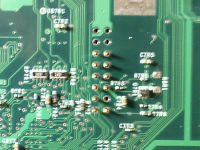
Once we have the pin header inserted into the proper LPC holes, pop a couple pieces of electrical tape on it to hold it into place and turn it upside down, you should have something that looks like this.
Next, you want to apply a solder to LPC holes 1-6 of course skipping number 4 since there is no pin coming out. Then, go ahead and apply just a tiny bit of solder to LPC holes 7-12. Just enough to close the hole. You don't want to use a ton of solder because the PCB will not lay down flat. Here is what mine looked like when I was done with the solder.
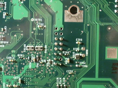
Next, lay the SmartXX PCB down on holes 7-12 so they fill the six holes in the middle of the board. Line up the other solder spots on the PCB so they line up with the areas that they solder to. Then, lay down some solder to cover the holes. See following image.
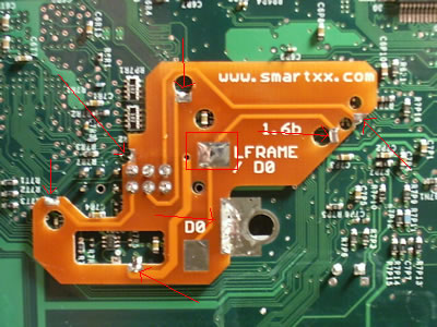
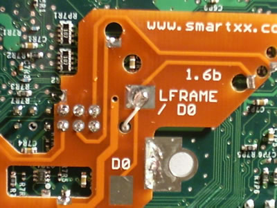
Next, hit the other areas with solder. Do a little at a time until the solder flows over and fills the spot it is supposed to fil. I put a red mark by each point. Also, put some solder down on the LFRAME area so you can then solder in the LFRAME wire to the PCB.
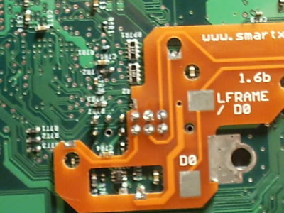
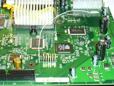
Here is a shot after LFRAME wire is soldered to PCB and routed through hole. The picture after that is the wire coming out the top to be soldered to the D0 point on the Xenium Ice Mod Chip.
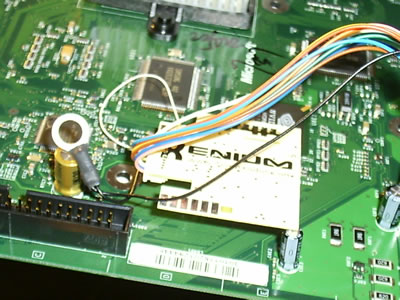
Finally, the external LED harness is connected to the chip and strung through the bottom of the case. I remove the controller ports to string it out. It is not necessary to do this. If you want these pics added, I'll be more than happy. Here is a final pic with the chip connectd and the LED Harness connected.
I hope that helps anyone. If you need extra images let me know.
TheModGod
-----------------------------
http://www.xbox-hq.com http://www.themodgod.com _________________ Good Deals: Death@Hand, funkydopenloven, StaticMind, Slamscaper, PorscheXboxter
Bad Deals: None Yet
Pending Deals: Vanguard
|
All times are GMT |Page 1 of 1
You cannot post new topics in this forum You cannot reply to topics in this forum You cannot edit your posts in this forum You cannot delete your posts in this forum You cannot vote in polls in this forum You cannot attach files in this forum You can download files in this forum