Posted: Sun Apr 21, 2013 11:51 am Post subject: Controller Fix
Hey people!
I baught a Xbox console few months ago.
The seller gave me 2 not working controllers with it for free.
I plugged them in the xbox and they don't get recognized by the system, like nothing is hooked up (I tried different consoles and plugs: they don't work).
Optically they look very nice though; that's why I actually don't want to just throw them away.
You can take a look at the pictures.
What I can tell is that they were opened before, since both stickers at the back were hurt when I got them.
Is there any way to fix these controllers/to spot the problem?
Or will I be better off slaughtering them and taking all the useful parts out such as the thumbsticks, gumpads etc.?
DSC01778.JPG
Description:
These are the both guys.
Filesize:
507.84 KB
Viewed:
501 Time(s)
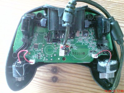
DSC01781.JPG
Description:
1 guy from the inside.
Filesize:
560.24 KB
Viewed:
502 Time(s)
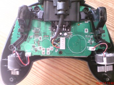
DSC01783.JPG
Description:
The other one.
Filesize:
497.42 KB
Viewed:
491 Time(s)
Amiga1200 V.I.P. Lifetime
Joined: Jun 19, 2012 Posts: 461
Posted: Sun Apr 21, 2013 5:59 pm Post subject:
^^ i've had pads that were a similar way....all looking good on the surface but fuckall going on the xbox side (or a computer with socket changer...nada)
in my case, the pads hadn't been opened up, it was like they just decided to "not work" according to the person who gave them to me!
what i had to do was REPLACE the entire cable! (always keep that breakaway plug bit...always comes in handy and they're the strongest part of the cable)
i got a sound cable from a fucked pad (PCB was utterly shagged) and soldered it to the working PCB pad (after removing it's fucked cable)
those things are NOTORIOUS for internal frays!
there's no real way to tell how far up the cable the fray may exist bar a continuity test on a multi-meter!
in some cases, albeit rare, the pad PCB itself could be fucked? it happens!
(MAKE sure your household mains supply is SURGE-DEFENDED and EARTHED...i cannot stress that enough!
f*ck, i've even had a megadrive cartridge, YES, a FIXED ROM get blanked because of a storm! all my tech acts up if it's NOT protected during a weather front)
........
anyway, try testing the cable continuity with a multi-meter and if you get a ZERO readout (or less than a 1/1) the cable is fucked! also check pathways on the pad PCB, it may have got "flashed/fried" in a power surge/bad weather front?
hopefully, it's just the cable so it can easily be transplanted from a donor (non-working) pad!
this isn't my area of course and the advice here is based off one man's personal experience in a world where NOTHING (at the time) existed for pad repairs!
it's possible google/duckduckgo may help but i'm not seeing much atm!
(i HATE search terms, they should be uniform but..
look in the tutorial section here, possibly something that can help?)
good luck to a fix, surely a real expert can chip-in here!?
[edit].....
i can't solder fine items for toffee (bad bone ilnesses) but replacing/swapping an xbox pad cable was really easy and required a dash of common-sense! (specific expertise is obviously a better asset) _________________ to all my friends... farewell and all the best to future prosperity... and remember, be excellent to each other!
quads V.I.P. Lifetime Xbox Version: 1.0, 1.6 Modded: softmod, smartxx
Joined: May 25, 2008 Posts: 176 Location: Elkhart, IN
Posted: Sun Apr 21, 2013 6:45 pm Post subject:
I usually just cannibalize em for parts and hit up ebay for more controllers. If it is the cable it isn't a bad fix really but you can find them so cheap I don't really bother.
GuitarGuy95 Xbox-HQ Enthusiast
Joined: Dec 24, 2012 Posts: 48
Posted: Thu Apr 25, 2013 6:15 pm Post subject:
Hey amiga!
Thanks for the quick and large answer!
I will try testing the cables with a multi meter, when I get time for it.
This really seems to be worth a try; problem is where do I get another broken controller , u know?
Well I'm defenetly going to try the method you speak off.
In case it is not the cable: what do you think is the better joice:
Acting like quads says and "cannibalize" the pads or selling them?
Anyway: I won't give up so fast and I'll let you hear how I'm doing when I find time for the operation!
forahobby Administrator
Joined: May 22, 2003 Posts: 23944 Location: NSW, Australia
Posted: Thu Apr 25, 2013 6:19 pm Post subject:
hey guitarguy, I've noticed you been getting involved in the forums, just thought id say it would be cool if you uploaded a avatar. You can pick one of the pre-defined ones too.. It just helps people remember you etc and get to know you better. 28 posts and climbing now.. Anyway, good to have you around the place mate. _________________ HQ Network:
www.xbox-hq.com | www.xboxone-hq.com | www.360-hq.com | www.c64-hq.com
Amiga1200 V.I.P. Lifetime
Joined: Jun 19, 2012 Posts: 461
Posted: Thu Apr 25, 2013 7:43 pm Post subject:
@ GuitarGuy95.
apart from the testing (and cable swap if need be) and another post suggesting "cannibalise" the parts...not really...
if the PCB/logic is fried/flashed in some way, the pad is just a paperweight but useful for all it's parts such as the contact pads, motors and plastic housing/buttons etc...
if the PCB is utterly FINE but you're shy of a working cable, you can use a psx/2 cable, it has more cores than an xbox pad cable giving you legroom (colours will vary so mark down your progress and keep track of any solder replacements as you go along, the psx/2 to xbox plug swap/solder will be quite difficult but not impossible!
there's various similar cables you can use but make sure they're 6-core (NO LOWER) with a shield/ground core.
..........
if the PCB/logic is fucked, not a lot you can do aside use it's parts/housing...
.....
hopefully, you get them working again, if not...sorry to hear that!
i'm all outta ideas right now...sorry!
(there's only 6 wires used on the xbox pads so if the donor/replacement cable has more, just fold/cut the excessive wires after you've soldered the others in place, better to have more ends than less and REMEMBER to use the GROUND/EARTH core on the xbox pad...wire WON'T be plastic shielded, it's bare but obvious! if donor/replacement cable DOESN'T have a GROUND but it has enough wires, substitute using a normal wire, as long as the pad is earthed/grounded, it's all good)
all the best! _________________ to all my friends... farewell and all the best to future prosperity... and remember, be excellent to each other!
GuitarGuy95 Xbox-HQ Enthusiast
Joined: Dec 24, 2012 Posts: 48
Posted: Sat Apr 27, 2013 1:20 pm Post subject:
Hey Hobbs!
Done.
Though this guy should actually move lol.
I'm very glad to be here, my pleasure .
See ya around, mate!
Amiga:
I really appreciate your super firendly feedback .
So what I am going to is checking wether the cable or the motherboard is fucked, right?
What i didn't understand (I am very bad at physics ) at which spot I have to test the cable/the PCB (which is the controllers board, right?).
And could you explain this earthed/ground-thing again?
I know that this probably sounds like I am a total moron (maybe because I am one at this theme ^^)...
But I'd like to excuse that lol.
Thank you very much, bro!
Amiga1200 V.I.P. Lifetime
Joined: Jun 19, 2012 Posts: 461
Posted: Sat Apr 27, 2013 5:23 pm Post subject:
^^ i'm no electronics expert, just using common sense!
okay, test each colour wire from the plug pins right up to the point they're affixed to the PCB, the little white block connecting the cable to the pad..
......
the ground wire is black but thicker than the other black wire, you'll notice it!
the insulation is a mere sleeve at the white plug end! (some come away in your hand once cable is disconnected from the PCB)
to keep it simple, just test each coloured wire from the plug right up to the PCB (black-black, red-red, green-green and so on) you're looking for a 1/1 continuity readout, that means the wires aren't frayed/broken along the way!
any less and and the cable is fucked (i'm hoping it is just the cable)
if the cable is sound, then the PCB is at fault, in which case, test the pathways, look for traces and test them as they go into/out of components!
....................
the pathways should ideally give a 1/1 readout as it's just a wire printed on perspex but the components are different with resistance/gate values so you'll get reading less than 1/1...this is normal! (it's a 0/1 that's bad news) ensure you test at the correct polarity! (and calibrate the multi-meter with the values of the components you're about to test for an accurate readout)
do some web surfing to find the values of each component and what the ideal readout on a multi-meter should be!
(test that cable first and make sure NOTHING is crossed/shorting, ensure all exposed wires are insulated using insulation/electrical tape)
sorry i can't be any more assistance here, i'm outta ideas!
.........
good luck! _________________ to all my friends... farewell and all the best to future prosperity... and remember, be excellent to each other!
GuitarGuy95 Xbox-HQ Enthusiast
Joined: Dec 24, 2012 Posts: 48
Posted: Sun Apr 28, 2013 1:29 pm Post subject:
amiga1200 wrote:
^^ i'm no electronics expert, just using common sense!
okay, test each colour wire from the plug pins right up to the point they're affixed to the PCB, the little white block connecting the cable to the pad..
......
the ground wire is black but thicker than the other black wire, you'll notice it!
the insulation is a mere sleeve at the white plug end! (some come away in your hand once cable is disconnected from the PCB)
to keep it simple, just test each coloured wire from the plug right up to the PCB (black-black, red-red, green-green and so on) you're looking for a 1/1 continuity readout, that means the wires aren't frayed/broken along the way!
any less and and the cable is fucked (i'm hoping it is just the cable)
if the cable is sound, then the PCB is at fault, in which case, test the pathways, look for traces and test them as they go into/out of components!
....................
the pathways should ideally give a 1/1 readout as it's just a wire printed on perspex but the components are different with resistance/gate values so you'll get reading less than 1/1...this is normal! (it's a 0/1 that's bad news) ensure you test at the correct polarity! (and calibrate the multi-meter with the values of the components you're about to test for an accurate readout)
do some web surfing to find the values of each component and what the ideal readout on a multi-meter should be!
(test that cable first and make sure NOTHING is crossed/shorting, ensure all exposed wires are insulated using insulation/electrical tape)
sorry i can't be any more assistance here, i'm outta ideas!
.........
good luck!
Thanks dude, no prob.
Gonna give it a try soon!
|
All times are GMT |Page 1 of 1
You cannot post new topics in this forum You cannot reply to topics in this forum You cannot edit your posts in this forum You cannot delete your posts in this forum You cannot vote in polls in this forum You cannot attach files in this forum You can download files in this forum